Computing the work function
The workfunction is defined as the work needed to move an electron from a surface to a point in vacuum sufficiently far away from this surface. It is a central quantity in surface science, vacuum science, catalysis, and other related fields as it characterizes a given surface; illustrating the presence of impurities, adsorbates, and possible surface reconstruction. It is typically measured using surface science techniques such as thermionic emission, the Kelvin probe method, etc. It has also served as an important measure in various theoretical models about metallic surfaces. On this page, we describe how to compute the workfunction using outputs from a DFT calculation performed using VASP. We detail best practices, required INCAR tags, and possible pitfalls.
| Mind: The workfunction is a property of a surface, not a bulk property. Hence, the content of this page only applies to systems with reduced dimensionality (such as surfaces) i.e. systems where there is expected to be a charge density-free region in at least one direction of the cell. |
Required quantities
The workfunction, , is computed using the expression,
Step-by-step instructions
Step 1: Ensure that the chosen structure has a large enough atom-free (i.e. charge density free) and field-free region in the direction of the surface normal. A good rule-of-thumb is to center the atoms in your cell and have anywhere between 8–12 Å of vacuum on either side in this direction.
| Warning: Not using enough vacuum causes a field within the vacuum region, leading to inaccurate values of the vacuum potential (see point 3). |
Step 2: Perform a ground state DFT calculation. We suggest setting PREC=Accurate. If your cell has a net dipole moment (i.e. it is not symmetric along the direction of the surface normal), we suggest switching on the dipole correction by using the following INCAR tags: LDIPOL, IDIPOL, DIPOL. The use of the dipole correction is crucial to obtaining a flat field-free region in the potential (c.f. next point). In addition to these tags, set the LVHAR=T to output only the Hartree and ionic potentials to the LOCPOT file.
| Tip: We recommend using only the Hartree and ionic potentials as the exchange-correlation potential decays very slowly in vacuum. Using the sum of the Hartree and ionic potentials allows for determining the workfunction with significantly less vacuum requirements (and hence lower computational cost). |
Step 3a: Compute the vacuum potential. Average the contents of the LOCPOT file along the lattice vectors of the surface (i.e. both directions perpendicular to the surface normal). Find the field-free region by determining the region of space where the potential remains constant. This value of the potential is the vacuum potential.
| Tip: There exist two vacuum potential regions, one for either direction of the surface normal. Depending on your system, one of the directions may be more relevant than another. |
Step 3b: Alternatively, VASP can compute the vacuum potential when you set VACPOTAV=T in the INCAR file.
You can then grep for the output in the OUTCAR file
grep upper OUTCAR
which gives the following example output:
vacuum level on the upper side and lower side of the slab 8.049 7.778
Step 4: Determine the Fermi energy
The Fermi energy is written directly to the OUTCAR file. grep for the following lines in the OUTCAR to get the Fermi energy in eV.
grep "Fermi energy" OUTCAR
Example

Consider an example of a carbon atom adsorbed on an fcc-Pt(111) surface. The structure of such a system is
Pt16C
1.0000000000000000
   5.5437171645025325    0.0000000000000000    0.0000000000000000
   0.0000000000000000    4.8009998958550284    0.0000000000000000
   0.0000000000000000    0.0000000000000000   20.0000000000000000
Pt C
16 1
Direct
   0.1250000000000000    0.0833333333333334    0.3302590208582500
   0.6250000000000000    0.0833333333333334    0.3302590208582500
   0.3749999999999999    0.5833333333333334    0.3302590208582500
   0.8750000000000001    0.5833333333333334    0.3302590208582500
   0.3749999999999999    0.2500000000000000    0.4434196736194167
   0.8750000000000001    0.2500000000000000    0.4434196736194167
   0.1250000000000000    0.7500000000000000    0.4434196736194167
   0.6250000000000000    0.7500000000000000    0.4434196736194167
   0.1250000000000000    0.4166666666666667    0.5565803263805833
   0.6250000000000000    0.4166666666666667    0.5565803263805833
   0.3749999999999999    0.9166666666666666    0.5565803263805833
   0.8750000000000001    0.9166666666666666    0.5565803263805833
   0.1250000000000000    0.0833333333333334    0.6697409791417500
   0.6250000000000000    0.0833333333333334    0.6697409791417500
   0.3749999999999999    0.5833333333333334    0.6697409791417500
   0.8750000000000001    0.5833333333333334    0.6697409791417500
   0.0000000000000000    0.0000000000000000    0.7597409791417501
Since the system has a net dipole moment (the bottom and top surfaces are not identical, one is clean and another has carbon adsorbed on it), we would need to use the dipole correction in our calculation. An example INCAR file for this system is,
LDIPOL  = T
IDIPOL  = 3
DIPOL   = 0.5 0.5 0.5
LVHAR   = T
PREC    = Accurate
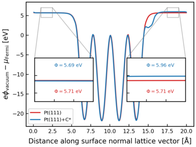
The Figure to the right shows a representative example of the vacuum potential obtained by averaging the contents of LOCPOT. This potential is referenced to the Fermi energy and is plotted against the distance along the surface normal (x axis) for two systems, fcc Pt(111) surface (in blue) and Pt(111) surface with a carbon atom adsorbed on one surface termination (Pt(111)-C*). The vacuum potentials are flat (i.e. constant) on either side (magnified in insets). The workfunction on either side of the slab are annotated in the insets as ; equal for both sides for the slab, but slightly higher for the case of Pt(111)-C*.
